

 English
 عربى
عربىThe Brushless DC Motor Driver: Where Efficiency, Noise, and Reliability Are Decided
When an appliance engineer opens a brushless DC motor datasheet, the numbers describe what the motor can do. The brushless DC motor driver decides whether the final appliance will actually deliver those numbers. It translates the control scheme into switching pulses for the three stator windings, senses rotor position, regulates current, and shuts the system down before a fault becomes a failure. The motor-and-driver pair, not the motor alone, sets the performance ceiling.
What a brushless DC motor driver actually controls
A brushless DC motor is a synchronous machine with permanent magnets on the rotor. Because there is no mechanical commutator, the stator current must be switched from one winding to the next in a precise sequence. The driver performs that switching: six power transistors form a three-phase inverter, and the controller inside the driver decides when to open and close each transistor.
Rotor position is read from Hall-sensor inputs or estimated from the motor's back-electromotive force. Either way, the driver closes the loop: sense the rotor, energize the correct winding, measure the current, adjust the PWM duty cycle. This is why the same motor can run quietly and efficiently on one driver and noisily on another.
A typical appliance-class BLDC driver contains:
- a three-phase inverter stage with six power switches;
- gate-driver circuitry that handles voltage and timing margins;
- rotor position sensing via Hall sensors or sensorless back-EMF estimation;
- current sensing and protection logic for overvoltage, overcurrent, and overheating.
The practical consequence is that a brushless DC motor driver is not a generic on-off switch. It is the control backbone of the appliance, and its quality determines how much of the motor's theoretical performance reaches the user.
Three control schemes, three performance levels
Almost every appliance BLDC driver runs one of three control strategies. The choice influences component cost, motor noise, and how efficiently the motor behaves across its speed range.
Trapezoidal (six-step) commutation
Each phase conducts for 120 electrical degrees at a time, so the terminal voltage resembles a staircase. Implementation is simple and inexpensive, and this approach remains adequate for many fans and blowers. The trade-off is a torque dip at every commutation event, which can become audible at low speed.
Sinusoidal commutation
Current in each phase follows a sinusoidal profile, so electromagnetic torque is steadier. Sinusoidal control needs a slightly more capable controller, but it visibly cleans up acoustic behavior. Air-cooler fans and heating-appliance blowers are common fits.
Field-oriented control
FOC, also called vector control, transforms the three phase currents into a rotating reference frame and controls stator current in two independent axes. It provides the best efficiency over a wide speed range and the smoothest low-speed operation, at the cost of more computation and engineering effort. Range hoods with several speed levels and premium fans have made FOC the reference solution.
| Control scheme | Torque smoothness | Implementation cost | Typical appliance fit |
|---|---|---|---|
| Trapezoidal (six-step) | Commutation ripple at each step | Low | Cooling fans, cost-sensitive blowers |
| Sinusoidal | Steady torque, low ripple | Medium | Air coolers, heating-appliance blowers |
| Field-oriented control | Smooth, strong at low speed | High | Range hood DC motors, premium fans |
There is no universal winner. The right choice depends on the speed range, the target price of the appliance, and the acoustic quality the market expects.
Electrical parameters to define before you source
When the motor is selected first, the driver is chosen against four electrical parameters. These are the boundaries where most mismatches happen.
| Parameter | Why it matters | Practical check |
|---|---|---|
| Supply voltage | Defines voltage stress and drive headroom | Keep the inverter rating above the motor back-EMF at maximum speed plus margin |
| Peak and continuous current | Appliance motors draw 2 to 3 times rated current at startup | Confirm the driver's peak current exceeds the motor's stall current |
| PWM switching frequency | Sets audible switching noise and switching loss | For indoor appliances, choose 20 kHz or above |
| Position sensing | Defines connector layout and control behavior | Match Hall-sensor spacing or validate the sensorless start routine |
Voltage tolerance deserves attention too. On battery-powered air coolers or solar-assisted installations, the bus voltage can fluctuate well outside its nominal level during load steps. The driver's absolute maximum input rating must cover those transients without entering repeated protection cycles.
For small appliance motors, the common bus voltages are 12 V, 24 V, and 48 V. Lower voltages simplify compliance testing; higher voltages reduce current for the same power and shrink wiring and connector losses. Keep the choice tied to the rest of the system, not only to the motor.
Matching the driver to the appliance load
The appliance load profile should drive the control decision, not the other way around.
Range hoods
A range hood needs constant airflow through a progressively oil-loaded filter, several speed levels, and low noise at night. A brushless DC motor with FOC control handles this combination best, because partial-speed efficiency is markedly better than with an induction motor. For engineers weighing the switch, we have covered how the range hood DC motor improves energy efficiency compared with traditional AC motors in practical operating conditions.
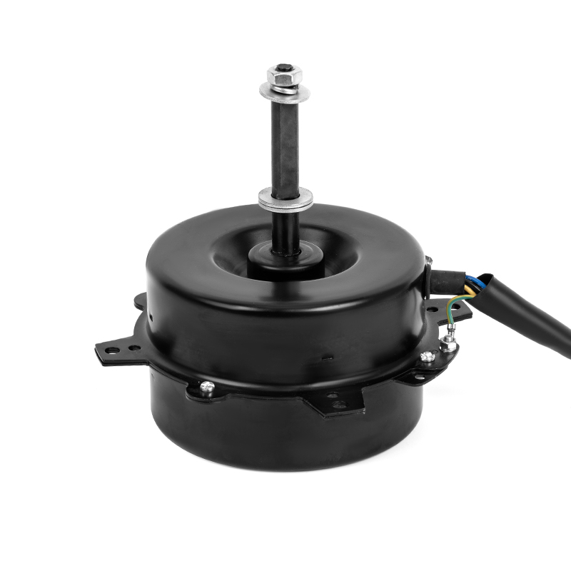
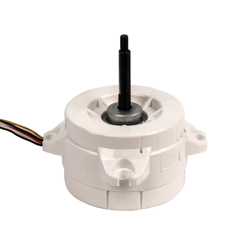 Small Range Hood DC Motor for Efficient Kitchen VentilationThis brushless DC motor is designed for range hoods, offering better partial-speed efficiency and quieter operation than traditional AC motors. It suits engineers seeking improved energy performance and reliable continuous airflow.View Product →
Air coolers and desktop fans
Evaporative air coolers run for long periods in a warm, humid environment, often from 12 V or 24 V supplies. Efficiency shows up directly in operating cost and battery life. An air-cooler DC motor designed for continuous duty rewards a sinusoidal or FOC driver with a wider useful speed range. For cost-sensitive desktop fans, six-step commutation remains a legitimate choice because the load is light and space for electronics is tight.
Practical advice for OEM buying decisions
Start with the operating profile, not with the motor. Write down the speed range, the torque needed at maximum speed, the number of starts per day, and the expected ambient temperature. These four inputs determine the motor size and the driver stage.
Then ask for startup evidence. A motor-driver pair can behave perfectly at rated speed and still struggle to start under load. Request a captured current waveform of the motor starting against the worst-case impeller; a trace that creeps instead of showing clean commutation steps is a warning sign.
Make thermal testing part of acceptance. Mount the driver inside the finished appliance, run it at nominal voltage and maximum ambient temperature, and measure the temperature rise of the power stage. Datasheet margins should not justify a hot enclosure.
Finally, check how much electrical data the motor supplier will share. Back-EMF waveform, phase inductance, Hall-sensor angles, and commutation offset are the inputs a driver designer needs. A manufacturer that can supply these, and that can develop motors from your drawings or samples, shortens the integration phase considerably. Miduo Electric Appliance, for example, builds small-power AC and DC motors for cooling fans, heating units, range hoods, and air coolers, and accepts custom development from customer drawings or samples.
Treat the driver and motor as one system
The practical takeaway is straightforward. A brushless DC motor driver is not an accessory that gets bolted on; it sets the efficiency, the acoustic quality, and the field reliability of the finished appliance. Define the load profile first, decide the control scheme second, verify the electrical boundaries, and then validate the complete motor-and-driver system inside the real enclosure.
Every appliance motor has two halves: the machine that turns and the electronics that decide when to turn it. The quietest motor on the bench is only as good as the switching logic that feeds it.
The sooner the driver enters the design conversation, the better the appliance performs.
For designers of range hoods, air coolers, and other small-power appliances, the driver is where the performance differential lives. Involve it early, ask the right questions, and verify the pairing under the conditions the appliance will actually meet. The result is a product that runs quieter, wastes less energy, and survives longer in the field.
 ++86 13524608688