

 English
 عربى
Two air coolers leave the same factory with the same blade, the same housing and the same airflow rating. One draws 42 W; the other draws 34 W. On paper the difference is the motor, but in practice it is the motor, the drive electronics and the exact point on the curve where the appliance holds the motor while it runs.
The conclusion first: the efficiency of a brushless DC motor is decided by three things you can actually engineer and check - the loss budget inside the motor, the loss budget in the electronics switching it, and the operating point the application forces it to run at. A datasheet peak is one point on a curve. What a customer pays for over ten years is a weighted average across real duty cycles, ambient temperatures and airflow resistance.
Get those three aligned and a small BLDC motor will typically cut input power by a quarter to a third against a shaded-pole or basic single-phase induction motor of similar frame size in a fan application. Get them wrong - oversize the motor, ignore the driver, let it run at 15% load - and a "high efficiency" motor quietly behaves like an ordinary one.
Efficiency Is a Curve, Not a Number
Efficiency is quoted as a single figure because single figures are easy to compare. In an appliance it behaves like a curve with a broad but finite top. In small brushless motors used in air coolers, cooling fans and range hoods, peak efficiency commonly falls in the 80-90% band when shaft power is measured with the motor's own driver included. The same motor pushed to 15-20% of rated torque often drops into the 50-60% range, because iron loss, windage and switching loss do not shrink when the load does. A shaded-pole motor of comparable size is usually quoted somewhere between 20% and 40%, which is why the swap is worth doing at all.
The top of the curve usually sits in the upper half of the speed range, at roughly 60-85% of rated torque, and it stays flatter through the middle of the range than most buyers expect. That flatness is the useful part: a motor sized for the real duty point, not for a worst-case start, spends most of its life near the top instead of on the slope.
Four things are worth demanding from a supplier before the conversation moves to price:
- An efficiency map, or at minimum three points - low, mid and rated load - rather than one peak figure.
- Input power measured at the appliance's design point, with the production impeller and housing, not on a bare shaft.
- A clear statement of whether the driver and its losses sit inside or outside the quoted number.
- Winding and magnet temperature after thermal steady state - two hours, not two minutes.
If the terminology is still settling, our basic knowledge points about motors is a reasonable place to check definitions before you compare quotations from different suppliers.
A peak figure measured at 24 V on an open shaft with a lab driver is not comparable with one measured at 12 V through a production board inside a sealed housing. Two suppliers quoting "88% efficient" may be describing two different machines.
Where the Losses Actually Go
Brushless motors win on efficiency for a specific reason: removing the brushes removes two loss paths at once. Brush contact creates friction, and it also creates a roughly constant voltage drop, which becomes a larger share of input power the lower the supply voltage. On a 12 V brushed motor, the brush interface alone can consume several percent of input power before the rest of the machine is considered.
What replaces the brushes is an inverter, and it is not free. A three-phase bridge with six MOSFETs adds conduction loss and switching loss, and a poorly matched driver can account for 10-20% of total losses. Six-step commutation is cheap and perfectly adequate for a fixed-speed fan; field-oriented control can recover a few points where the motor spends time at partial load, at the cost of a faster microcontroller and more engineering time.
| Loss mechanism | Typical share of total losses | Primary design lever |
|---|---|---|
| Stator copper (resistive) | 30-45% | Copper fill factor, current density, thermal path to the housing |
| Iron (hysteresis and eddy current) | 15-25% | Lamination grade and thickness, flux density, slot geometry |
| Drive electronics (conduction and switching) | 10-20% | MOSFET on-resistance, switching frequency, modulation scheme |
| Bearings, windage and rotor drag | 5-15% | Bearing type and preload, shaft alignment, impeller balance |
| Stray and harmonic losses | 3-10% | Slot-pole combination, skewing, manufacturing tolerances |
Two details matter more than most spec sheets suggest. Lamination grade is the first: moving to a thinner, higher-resistivity steel reduces the eddy-current part of iron loss, which is the portion easiest to influence. Slot-pole combination and skewing is the second: they shape stray and harmonic losses and, just as importantly, the noise the appliance makes at its quietest speed setting.
A motor that measures eight points higher on a bench can lose that advantage the moment it is bolted into a housing with a different impeller and a longer duct.
How Load and Temperature Move the Operating Point
Fan and blower loads follow two approximate rules: torque rises with the square of speed, and shaft power with the cube. Halving the speed cuts airflow to about half and cuts shaft power to roughly an eighth. That is the strongest argument for variable speed in range hoods and air coolers, because most of the energy is spent at the top of the speed range while most of the operating time is spent well below it.
The reverse is also true. In an appliance, efficiency is not a property of the motor alone; it is a property of the motor plus the air path. A clogged filter, a kinked duct or a slightly undersized grille raises static pressure, increases the torque the impeller demands at the same speed, and slides the motor down the right-hand side of its curve. A motor with a generous peak can still finish its life at 60% efficiency because the air path was never matched to it.
Temperature changes the numbers as well. Copper winding resistance rises about 0.39% per degree Celsius, so a winding that heats from 25 to 90 degrees adds roughly a quarter to its resistive loss at the same current. Permanent magnets lose flux as they warm - sintered NdFeB around 0.11-0.12% per degree Celsius - so the torque available at 100 degrees is measurably lower than the catalogue torque measured at room temperature. Choosing a heavier magnet grade or a better thermal path to the housing is a cost decision, not a technical one.
Every motor has a fixed loss floor: bearing drag, windage and switching loss that never disappear at low load. This is why efficiency falls toward zero as speed approaches zero, and why "efficiency at very low speed" is a misleading question. The useful question is total energy consumed across the duty cycle.
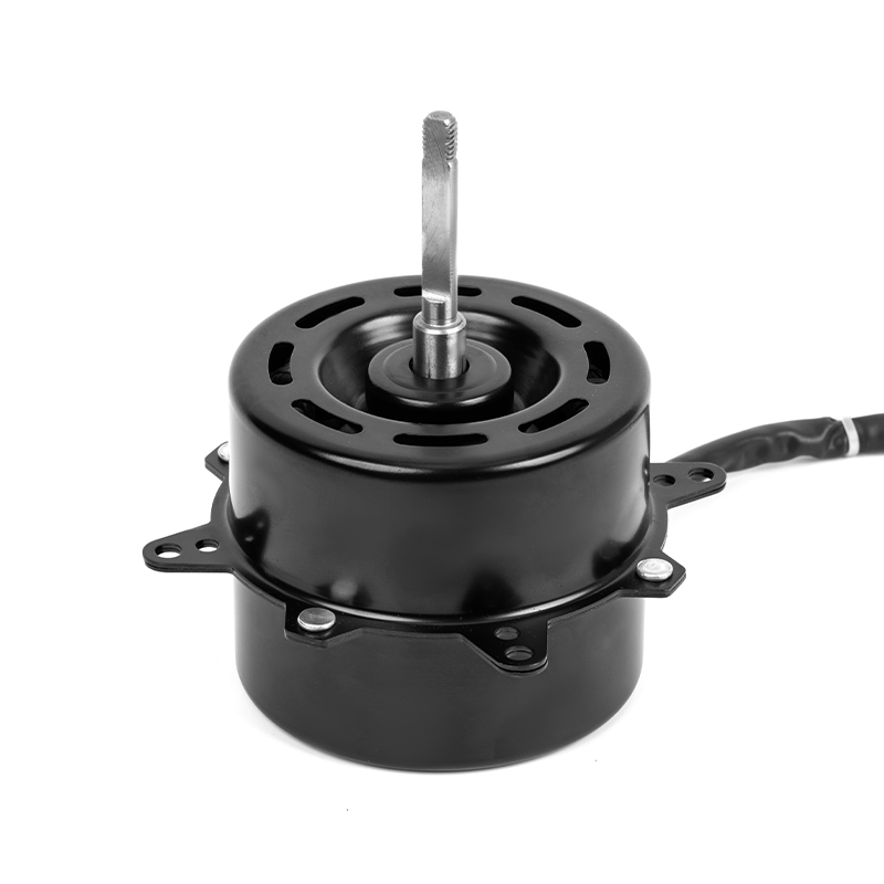
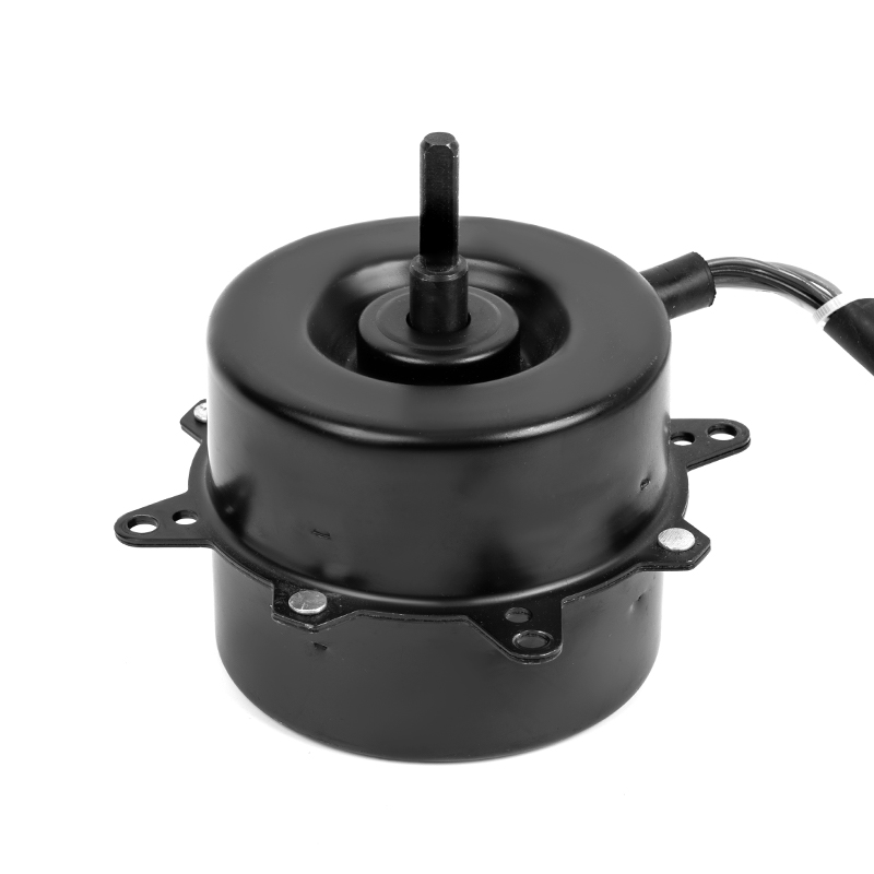
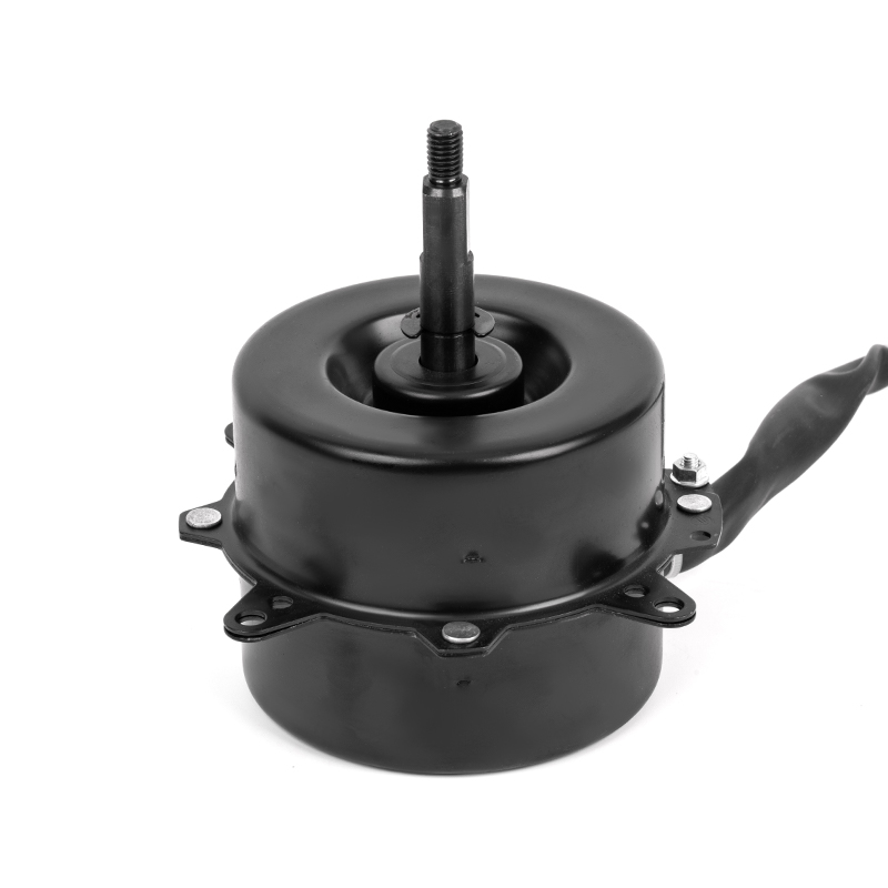
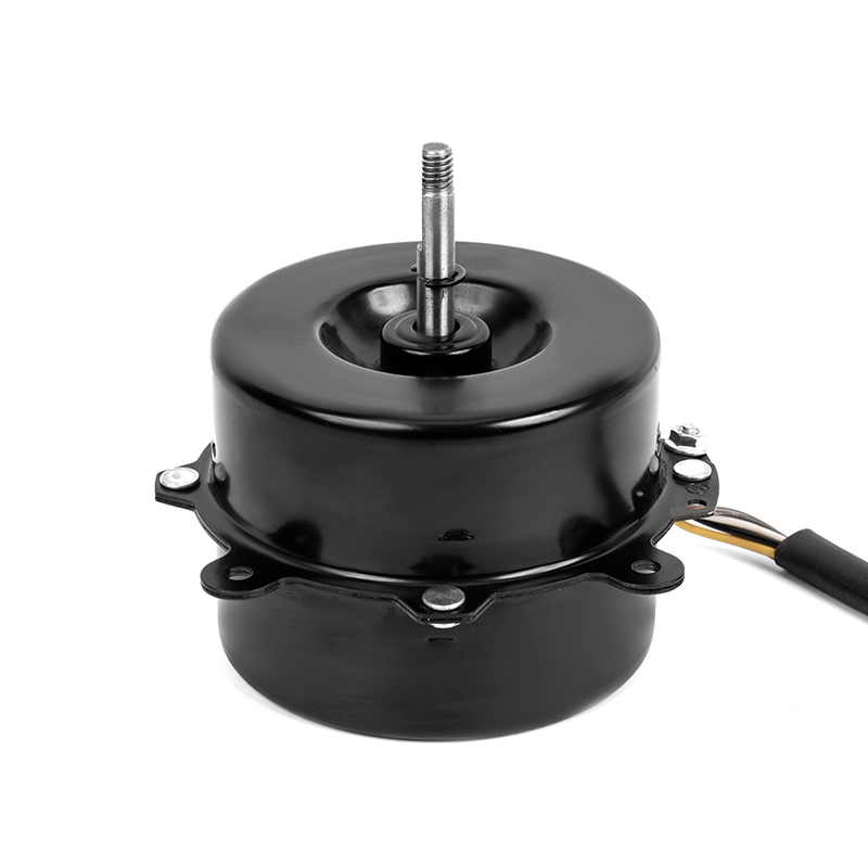
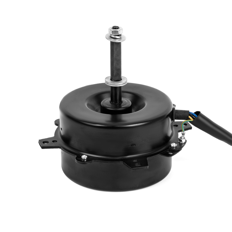
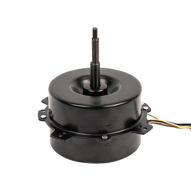
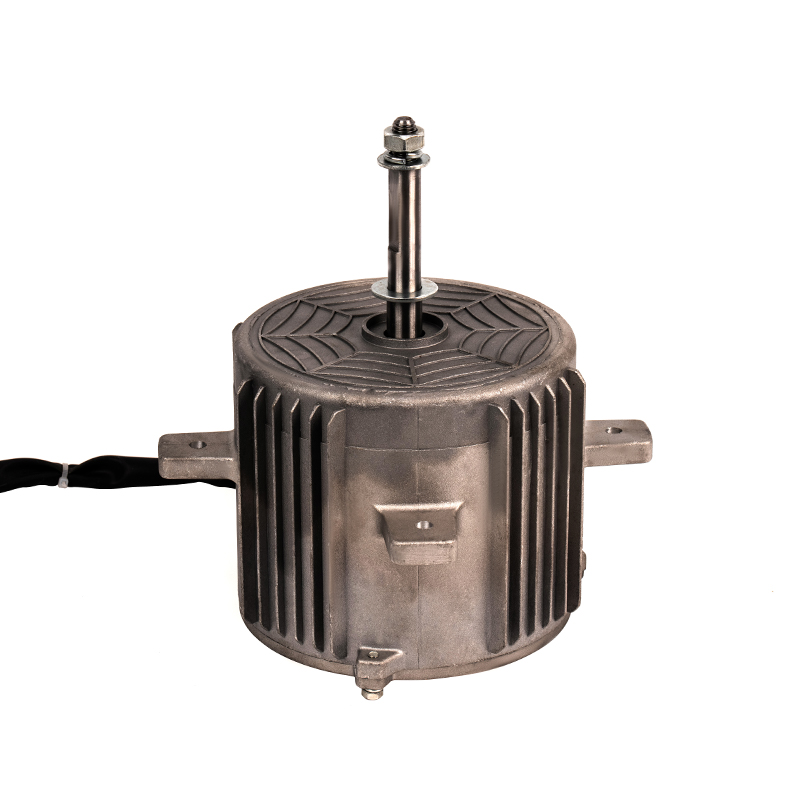
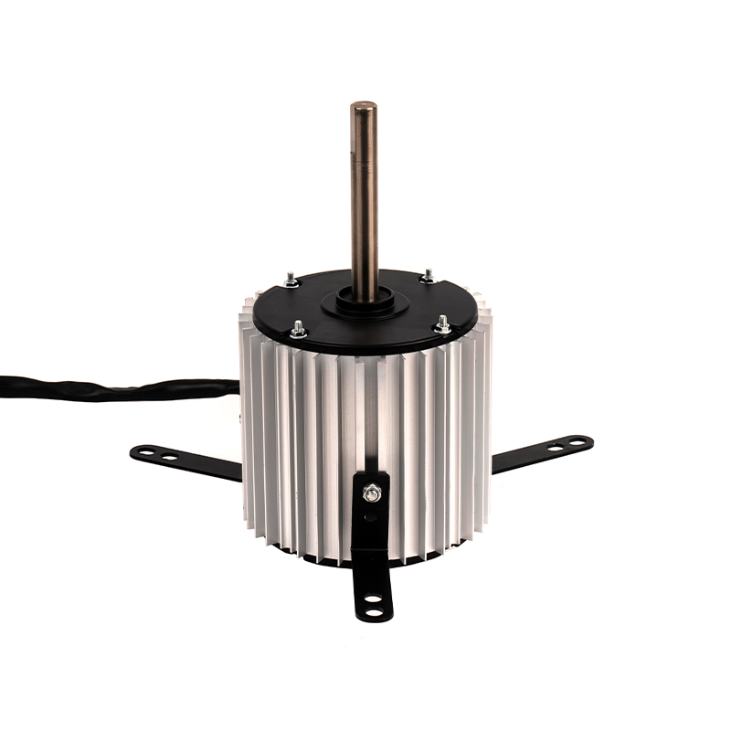
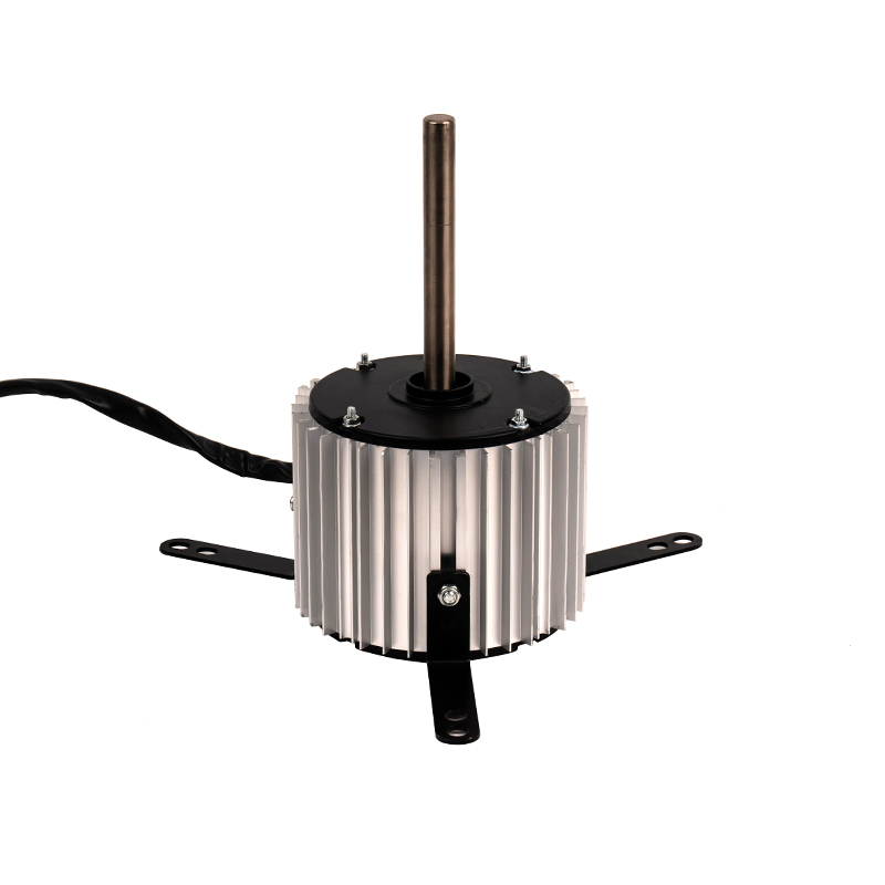
Air coolers illustrate the problem well. They run for hours at conditions that drift with the weather, so the motor has to hold a reasonable efficiency across a wide band rather than at one flattering point. That is the brief we design air cooler motors against.
AC or BLDC: Matching the Motor to the Appliance
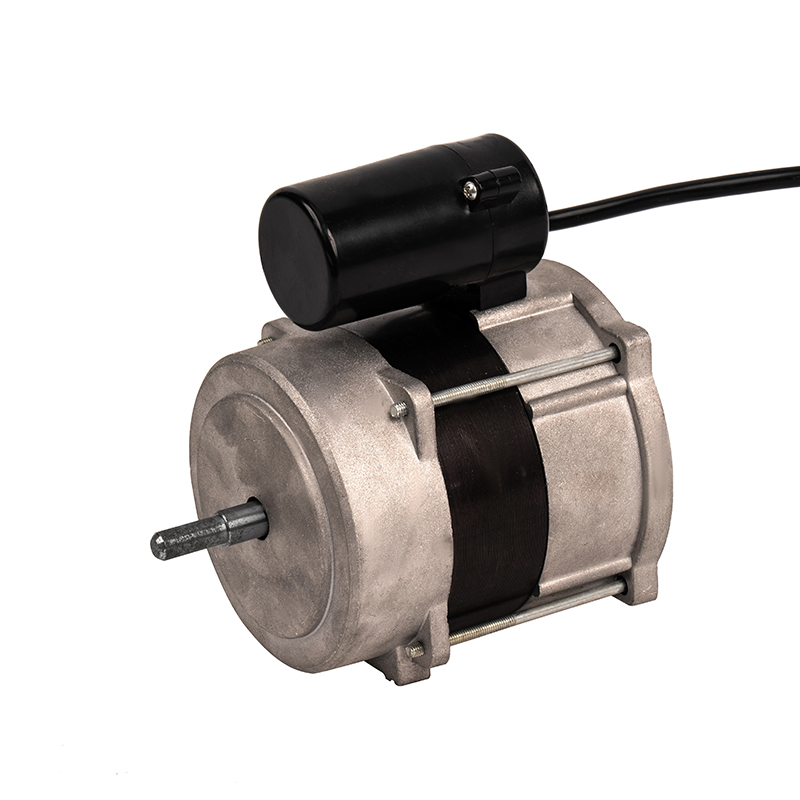
Brushless is not automatically the right choice. A single-phase capacitor-run motor has no electronics, no rotor position sensing, no firmware and very few parts. In a fixed-speed appliance with a short daily duty cycle, the energy saved by a BLDC may not repay the added cost inside the product's life. That calculation changes as soon as the load varies, the duty cycle gets long, or the appliance is expected to be quiet at low speed.
When the AC alternative still wins
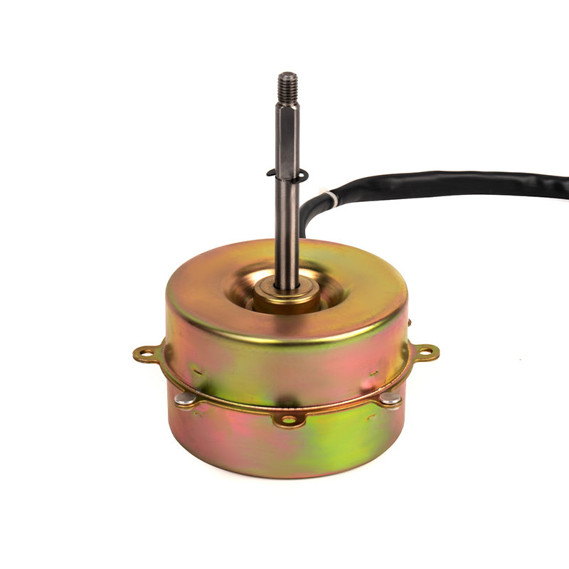
Fixed-speed operation, aggressive cost targets, dirty or unstable mains supply, and a short duty cycle all favour a single-phase asynchronous motor. If the appliance only ever needs one airflow and runs twenty minutes a day, the honest engineering answer is usually the simpler machine.
Range hoods sit on the other side of that line. Suction demand rises and falls with what is on the hob, and the gap between a gentle simmer and a hot pan is a factor of several in airflow. A DC motor plus control lets the hood follow the load instead of switching between three taps, and that is where most of the energy saving originates - not from the motor in isolation. We looked at the comparison in more detail in an article on how range hood DC motors improve energy efficiency compared with traditional AC motors.
What to Verify Before You Approve a Motor
Verification is cheaper than rework. A bench test at the design point takes half a day and answers questions a datasheet cannot.
- Measure input power at the appliance's normal supply voltage, with the production driver, at the design duty point rather than the motor's rated point.
- Measure shaft torque and speed at the same time. Efficiency is torque times angular speed divided by electrical input power; estimating torque from current is only acceptable as a first pass.
- Run at least 90 minutes before recording data, so windings and magnets reach thermal steady state.
- Repeat at the low and high ends of the control range and at worst-case ambient temperature.
- Compare current draw against the approved sample, using a tolerance band you are willing to enforce; plus or minus 10% on current and 5% on speed covers normal production spread in small motors.
One hour of testing at the real duty point usually costs less than a single field-return batch. If a quoted efficiency cannot be reproduced in your own housing, it will not appear on the end user's electricity bill either.
We build both AC and DC motor lines for these applications - cold air motors, heating motors, plastic-encapsulated oil fume motors and the DC range - and we develop to customer drawings or samples where a standard series does not fit.
Daily capacity above 80,000 units matters here in a different sense: the sample you approve has to be reproducible at volume, and consistency across a shipment is worth more than a peak figure only the prototype can reach.
Brushless DC motor efficiency is a system property. The motor contributes one loss budget, the driver contributes another, and the impeller, duct and ambient temperature decide where on the curve the appliance actually lives. None of that can be settled by comparing peak numbers in two quotations. The work order is straightforward: define the real duty point, ask for efficiency at that point with the production drive, test it warm and inside the real housing, and treat the gap between peak and operating efficiency as the number that shows up on the meter.
If no standard series fits that operating point, the motor can usually be developed to it - which is how most small appliance motors on the market arrived at their present shape in the first place.
 ++86 13524608688